Hard Surface Prop 1: Blockout
Standards (3)
GD.17.4Art & Design Fundamentals
Apply elements and principles of art and design to develop game environments, characters, and props for use in interactive 3D games.[^12]AV.17.83D Animation Fundamentals
Design and model props, vehicles, and characters to demonstrate core animation principles (e.g., weight, timing, visual storytelling); develop and apply rigging systems to enable animation using keyframing and/or match moving.[^10]10.4Building & Refining Concepts
Develop, test, and refine concepts through models, mock-ups, or prototypes that move ideas toward implementation.
The task
Build one low-poly hard surface prop using edit mode tools and non-destructive modifiers. Something mechanical or constructed: a weapon, a piece of equipment, a vehicle part, a container, or a device.
This is a blockout. The goal is a clean, correctly proportioned shape with good edge flow, not a finished, textured asset. That comes later.
Before you start
- Edit Mode Basics (
BLND-104) - Modifiers Introduction (
BLND-105)
Prop Examples & Reference Ideas
If you aren’t sure what to build, choose one of these classic hard-surface props. Each one tests a specific combination of edit mode cuts and modifier workflows:
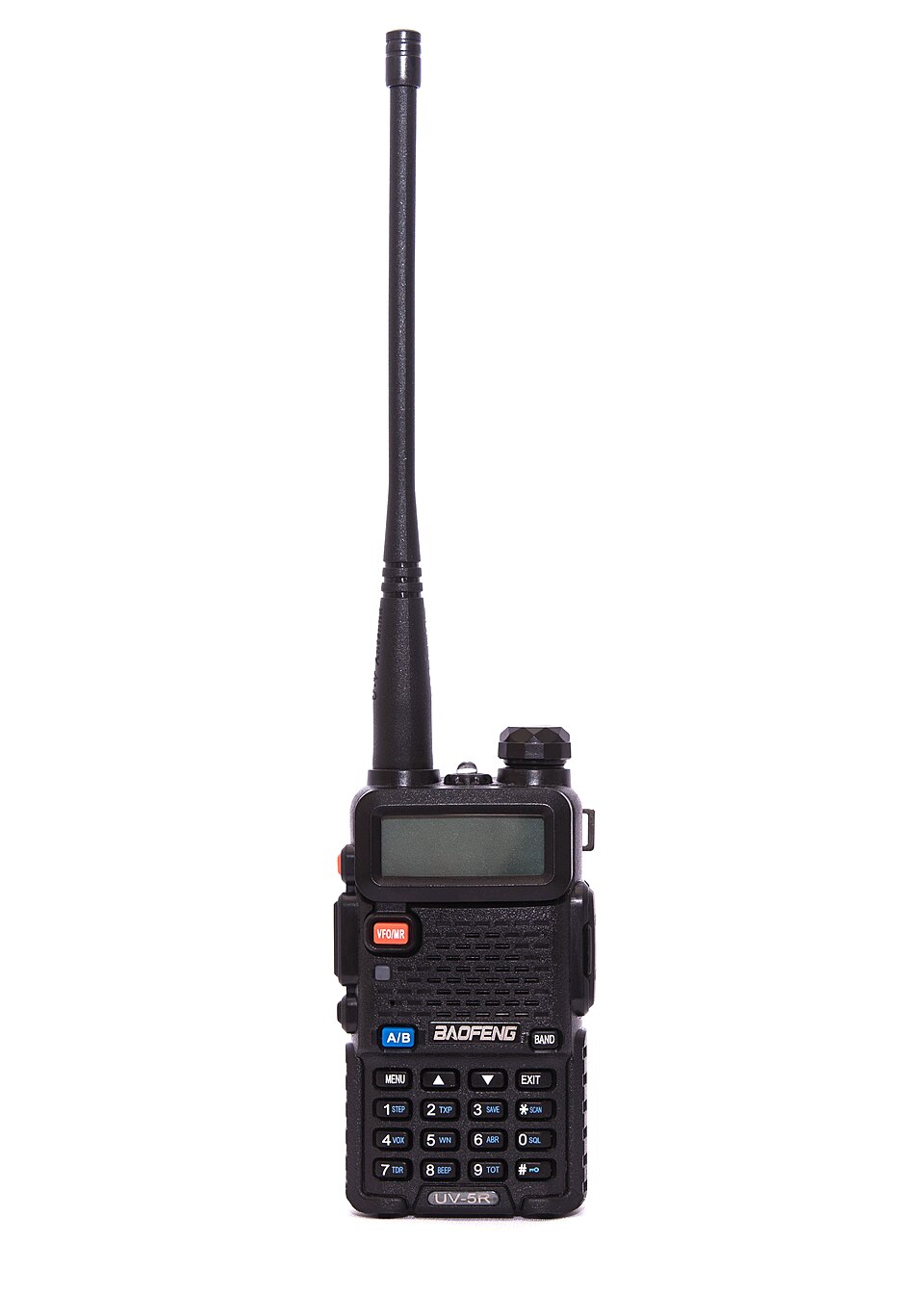
1. Tactical Walkie-Talkie
A handheld radio with distinct functional elements: beveled main housing, recessed display, inset speaker grill, antenna cylinder, and volume knobs.
- Base Shape: Cube scaled on Z
- Edit Mode:
Ito inset speaker grill & screen,Eto extrude knobs & antenna,Ctrl+Rfor grip grooves - Modifiers:
Bevel(casing edges),Mirror(symmetric chassis)
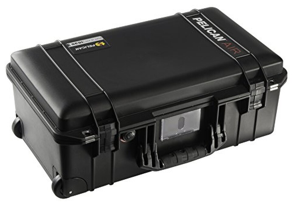
2. Reinforced Hard Case
A Pelican-style equipment crate. High structural visual interest with molded ridges, latches, corner protectors, and heavy carry handles.
- Base Shape: Flattened Cube
- Edit Mode:
Ctrl+Rloop cuts across the lid,Eto pull out reinforcing ribs,Ifor recessed latch pockets - Modifiers:
Mirror(X and Y symmetry),Bevel(rounded bumper edges)
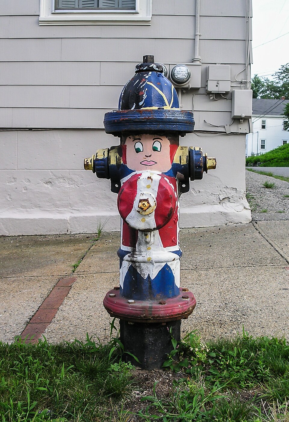
3. Municipal Fire Hydrant
A classic cylindrical hard-surface test. Features stepped diameter flanges, domed top cap, pentagonal operating nut, and side nozzle ports.
- Base Shape: 16-sided Cylinder
- Edit Mode:
E+Sto extrude flanges,Ctrl+Rfor ring control - Modifiers:
Boolean Difference(side nozzles or bolt holes),Bevel(cast iron rim highlights)
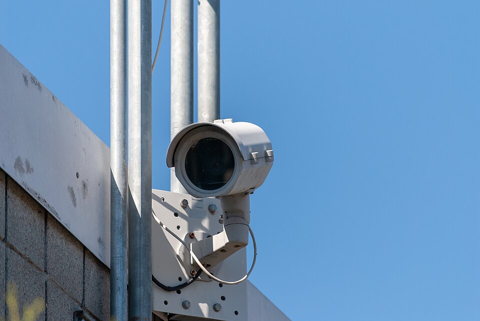
4. Security Camera / Sensor
Combines angular mounting brackets with cylindrical optic housing, sun visor shield, and a multi-axis swivel joint.
- Base Shape: Cylinder body + Cube mounting arm
- Edit Mode:
IandEinward for camera lens aperture,Ctrl+Rto bevel elbow joints - Modifiers:
Solidify(sun shield canopy),Bevel(machined chassis edges)
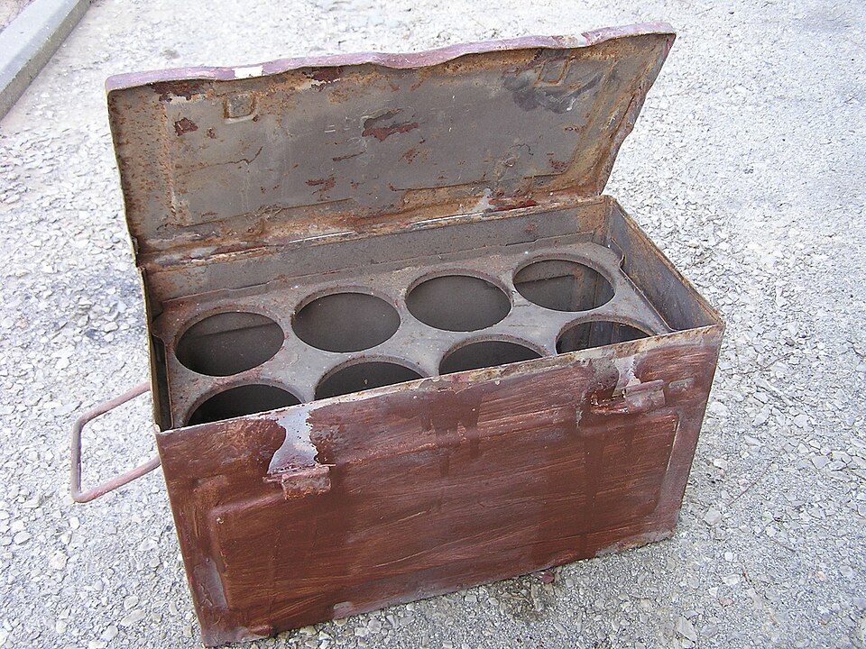
5. Military Ammo Crate
Sturdy sheet metal canister with stamped indents, clamping latch, perimeter seal rim, and top folding wire handle.
- Base Shape: Rectangular Cube
- Edit Mode:
Iand slight negativeEfor stamped side recesses, loop cuts for rim lip - Modifiers:
Mirror(symmetrical half),Bevel,Solidify(sheet metal brackets)
Steps
Step 1 — Pick a prop and gather reference
Choose something with clear mechanical shapes: flat panels, cylindrical sections, and a couple of raised or recessed details. You can pick from the examples above or choose your own prop (e.g., a sci-fi power cell, wall electrical box, or sci-fi door lock).
Find two or three reference photos from different angles before opening Blender. Save them to your 00_Reference folder or load them into PureRef.
Step 2 — Block the base form
Start from a primitive close to the object’s overall silhouette (usually a Cube or Cylinder). Get the primary proportions right before adding any cuts or detail. Compare against your reference photos constantly.
Remember to set your primitive’s initial vertex or segment count in the F9 operator panel when you first create it.
Step 3 — Build out the detail
Switch to Edit Mode (Tab). Using extrude, inset, and loop cuts, build out the secondary shapes:
- Inset (
I) to create panel borders, recessed screens, and structural rims. - Extrude (
E) to push out knobs, raised handles, vents, and housings. - Loop Cut (
Ctrl + R) to add edge loops where shapes need to step or bend.
Tip: If the prop is symmetric, delete half the mesh, set the object origin on the centerline seam, and add a Mirror modifier.
Step 4 — Apply your modifiers with intention
Add modifiers non-destructively to shape and polish the mesh:
- Add a Bevel modifier to catch light along the hard edges without permanently baking geometry.
- If using Subdivision Surface, place supporting loop cuts close to sharp corners to keep key mechanical edges crisp.
- If using a Boolean modifier to cut holes or ports, inspect the cut in Edit Mode to ensure geometry remains intact.
Keep modifiers live and unapplied in your modifier stack.
Step 5 — Clean the mesh
Run a cleanup pass on your model:
- In Edit Mode, select all vertices (
A) and press M → By Distance to weld any duplicate vertices. - Turn on Face Orientation in the Viewport Overlays dropdown. Ensure the entire exterior of your mesh is blue (pointing outwards). If any faces are red, select all and press Shift + N to recalculate normals outside.
- Check for non-manifold edges, stray floating vertices, or overlapping coplanar faces.
Step 6 — Check the silhouette
Test your model’s readability:
- Switch your viewport shading to flat or matcap silhouette mode (or apply a temporary matte dark material).
- Orbit around and inspect the front, side, top, and 3/4 perspective views.
- Does the prop immediately read as what it’s supposed to be without textures or colors? If not, adjust primary proportions before moving on.
Step 7 — Render and post
- Set up a simple 3-point lighting rig and a clean backdrop plane in Blender.
- Frame a camera view that highlights the prop’s most interesting angles and surface relief.
- Render a clean still image (
F12). - Take a viewport screenshot with Wireframe or modifier settings visible to show your non-destructive stack.
- Post your work to your Google Sites Portfolio on your Coursework page with the standard write-up, your reference images, and a brief reflection.
Submit
.blend file (with all modifiers live and unapplied) saved in your project folder (01_Projects).Rubric
Assessment Rubric
| Criteria | Proficient (4-5 pts) | Developing (2-3 pts) | Beginning (0-1 pt) |
|---|---|---|---|
| Edit Mode Construction | Cleanly utilizes Extrude (E), Inset (I), and Loop Cuts (Ctrl+R) to build accurate secondary forms and mechanical surface details. | Relies on basic transforms with limited inset/extrusion; some awkward geometry or uneven edge flow. | Missing secondary detail; geometry built incorrectly or primitives unedited. |
| Non-Destructive Modifiers | Modifiers (Bevel, Mirror, Boolean, Solidify) are configured thoughtfully in the stack and left live/unapplied. Origins properly aligned for mirroring. | Modifiers applied prematurely, or stack order causes visible artifacts/shading pinching. | No modifiers used, or destructive tools applied without non-destructive controls. |
| Mesh Cleanliness & Topology | No duplicate/overlapping vertices (Merge by Distance applied); normals point consistently outward; no non-manifold holes or broken geometry. | A few doubled vertices or minor inverted normals; slight shading artifacts around cuts. | Significant topology errors, doubled vertices, inverted normals, or degenerate faces. |
| Proportion & Silhouette Readability | Prop silhouette reads immediately from multiple viewpoints (front, side, 3/4); proportions closely match real-world reference. | Silhouette reads from one primary angle but appears distorted or disproportionate from other views. | Prop silhouette is unrecognizable or proportions clash heavily with real-world reference. |
| Portfolio & Documentation | Portfolio post includes final render, viewport wireframe showing modifier stack, reference images, and a written reflection on modifier choices. | Portfolio post contains render and basic write-up, but lacks reference images or modifier stack proof. | Missing portfolio post or incomplete deliverable. |
Notes
- Keep modifiers unapplied when you submit. Part of what’s being evaluated is whether you used them non-destructively rather than committing early. You will learn when applying is appropriate in a later unit.
- A messy Boolean is the most common way this assignment goes wrong. If a Boolean cut looks fine in shaded view but creates jagged triangulation or overlapping edges in Edit Mode, don’t ignore it. Clean geometry now saves real pain when this prop gets UV unwrapped in the next unit.
- Real hard surfaces have rounded edges. Perfectly sharp 90-degree computer graphics edges look fake because real objects have microscopic bevels that catch highlights. A subtle Bevel modifier makes your blockout look tangible and grounded.